Theremin — An Antenna That Plays Music
Building a working theremin from scratch — three failed circuit approaches, a fabricated PCB, and the physics of playing an instrument you never touch.
- Analog Circuit Design
- EAGLE
- Multisim
- PCB Fabrication

The first time I saw a theremin, it was Sheldon Cooper playing one on The Big Bang Theory. An instrument played by moving your hand through empty air — no keys, no strings, no contact at all — was not a thing I knew existed. I took the question straight to my electromagnetism professor: how does that even work? The answer sent me down a real rabbit hole — electromagnetic theory, antennas, waves, a dozen circuit variations, small prototypes wired up on a breadboard just to see which approach actually behaved. This was the project that made it click why I loved electronics: that constant back-and-forth between hardware and the logic driving it. A working theremin, from loose components up, ending on a fabricated PCB.
The trick is that the antenna never radiates anything#
Call it an antenna and your first instinct is radio: something broadcasting, something receiving. A theremin’s antenna does neither. It’s just one plate of a capacitor, sitting in open air, waiting for the other plate to show up. That other plate is your hand.
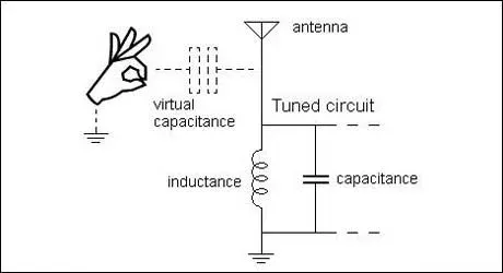
There’s a real physics distinction worth being precise about here: an antenna radiating a signal is working in the far field — energy that detaches and travels outward, which is how a radio actually gets anywhere. What a theremin’s antenna does instead is near-field coupling: a reactive field bound to the rod, decaying within centimeters, never travelling anywhere. It’s a capacitor plate shaped like an antenna, not a transmitter.
Wire that rod into an LC oscillator and its resonant frequency becomes a function of whatever capacitance the rod sees — hand included. The catch: a hand at a normal distance changes that capacitance by picofarads, millionths of a millionth of a farad. At audio frequencies that shift is undetectable; the oscillator would need an inductor the size of a dinner plate to notice it. Push the oscillator up into the hundreds of kilohertz instead, and the same tiny capacitance change becomes a frequency shift of kilohertz — big enough to work with, but now much too high a pitch to hear.
Two frequencies you can’t hear, beating into one you can#
So the theremin cheats a second time: build a second oscillator, fixed, at nearly the same frequency as the first, and mix the two together. Two close radio frequencies beating against each other produce a difference tone right in the audio range — the same heterodyning principle every superheterodyne radio receiver runs on, just repurposed to make music instead of tune stations. Summing two waves a small offset apart makes the offset itself audible:
The right-hand side is a single fast tone near — still hundreds of kilohertz, still inaudible — riding inside a slow envelope at . Move a hand and changes; keep itself under 20 kHz and that envelope is the note you hear.
Ours had one deliberate corner cut: a real theremin also has a volume antenna, played with the other hand — and it isn’t a second copy of the pitch circuit. It runs on a different trick entirely: its own hand-sensitive oscillator feeds a band-pass filter tuned to sit right at that oscillator’s resting frequency. Move a hand close and the oscillator drifts off that peak, so the filter’s output level falls. A diode detector smooths that falling level into a control voltage, and that voltage sets the gain of a VCA (voltage-controlled amplifier) sitting between the pitch tone and the speaker. The volume hand never makes a sound of its own — it turns a dial on the sound the pitch hand is making.
We built pitch-only. Getting one oscillator pair to track cleanly against a moving hand was hard enough for a first build — a second resonant stage, tuned separately, would have doubled the tuning headaches for a feature we could demo just fine without.
Three circuits, in order of how many I gave up on#
Before any of this became the schematic below, it was three separate attempts, each one teaching me why the previous one wasn’t going to work.
Attempt 1: digital, with logic gates. My first instinct was to build the two oscillators out of NAND gates instead of discrete transistors — a gate with its output fed back through a resistor into a capacitor-grounded input will happily oscillate, and the frequency is just a function of that RC time constant. Simple to reason about, simple to simulate. What it wasn’t was a sine wave — a NAND-gate oscillator swings hard between rail and ground, so the “audio” coming out the other side of a differential op-amp stage was a buzzy square wave with none of the pitch smoothness a theremin is supposed to have.
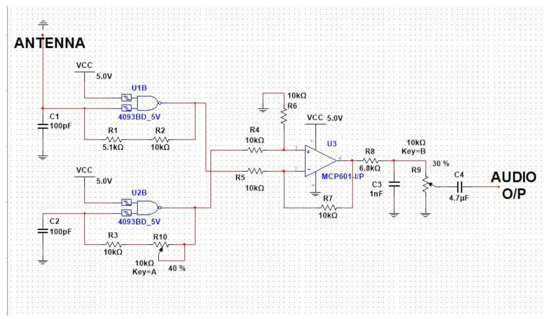
Two NAND-gate astable oscillators (4093 IC) into a differential op-amp — antenna capacitance detunes one gate’s timing, the op-amp takes the difference.
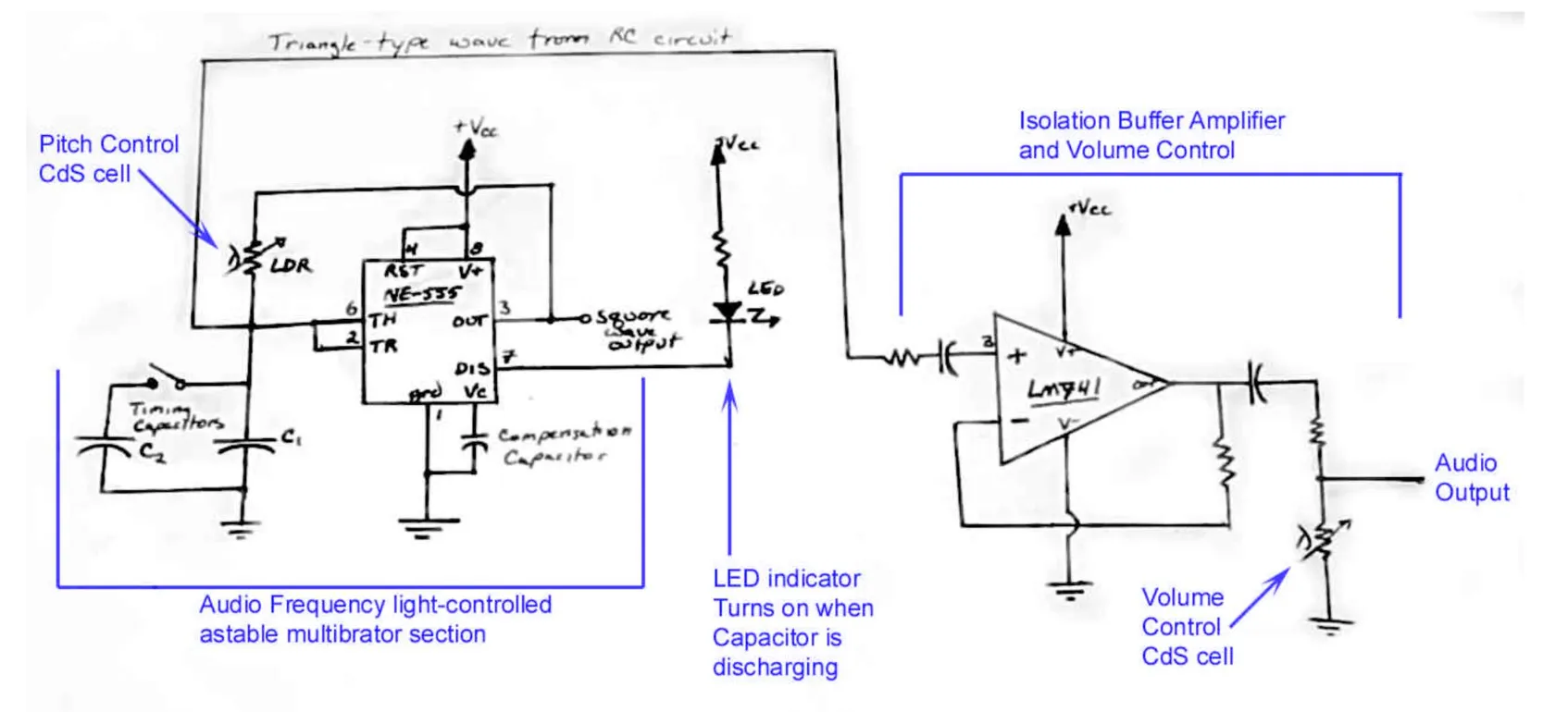
Attempt 2: optical, with a photoresistor. Frustrated with the digital version, I detoured entirely: an NE555 timer wired as an astable multivibrator, its frequency set by an RC network where the resistor was a CdS photocell instead of your hand. More light, lower resistance, higher pitch — an instrument played with a flashlight instead of a field. It worked, and it was genuinely fun, but it wasn’t a theremin anymore. The whole point was proximity sensing through a capacitive field; swapping that for a light sensor solved a different, easier problem.
Attempt 3: analog — the final design#
Two Colpitts oscillators built around 2N5484 JFETs, one tied to the antenna, one fixed as a reference, both landing around 410 kHz. This is the circuit in the diagrams above, and it’s the one that actually made it onto a board.
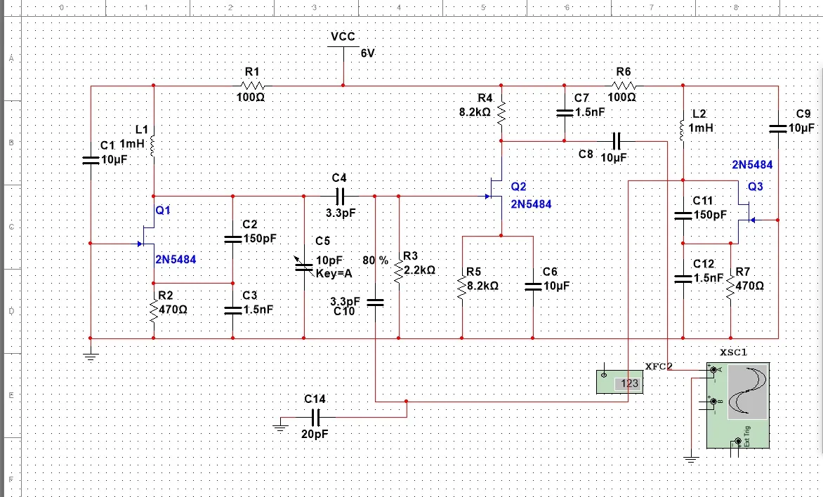
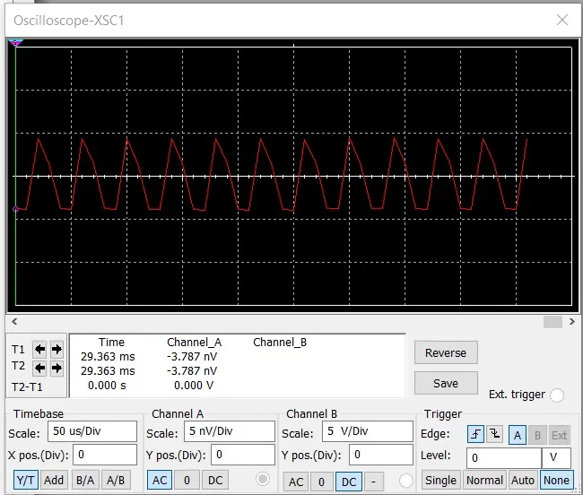
The mixer, Q2, is wired as an active rectifier rather than a plain diode mixer, which matters more than it sounds like it should: a diode mixer’s output impedance changes with signal level, so whatever you plug in afterward — a cable, an amplifier’s input stage — loads it down and drags the pitch with it. The active rectifier decouples output from input, so the note you’re playing doesn’t shift depending on what’s listening to it.
From schematic to a board that could be wrong in new ways#
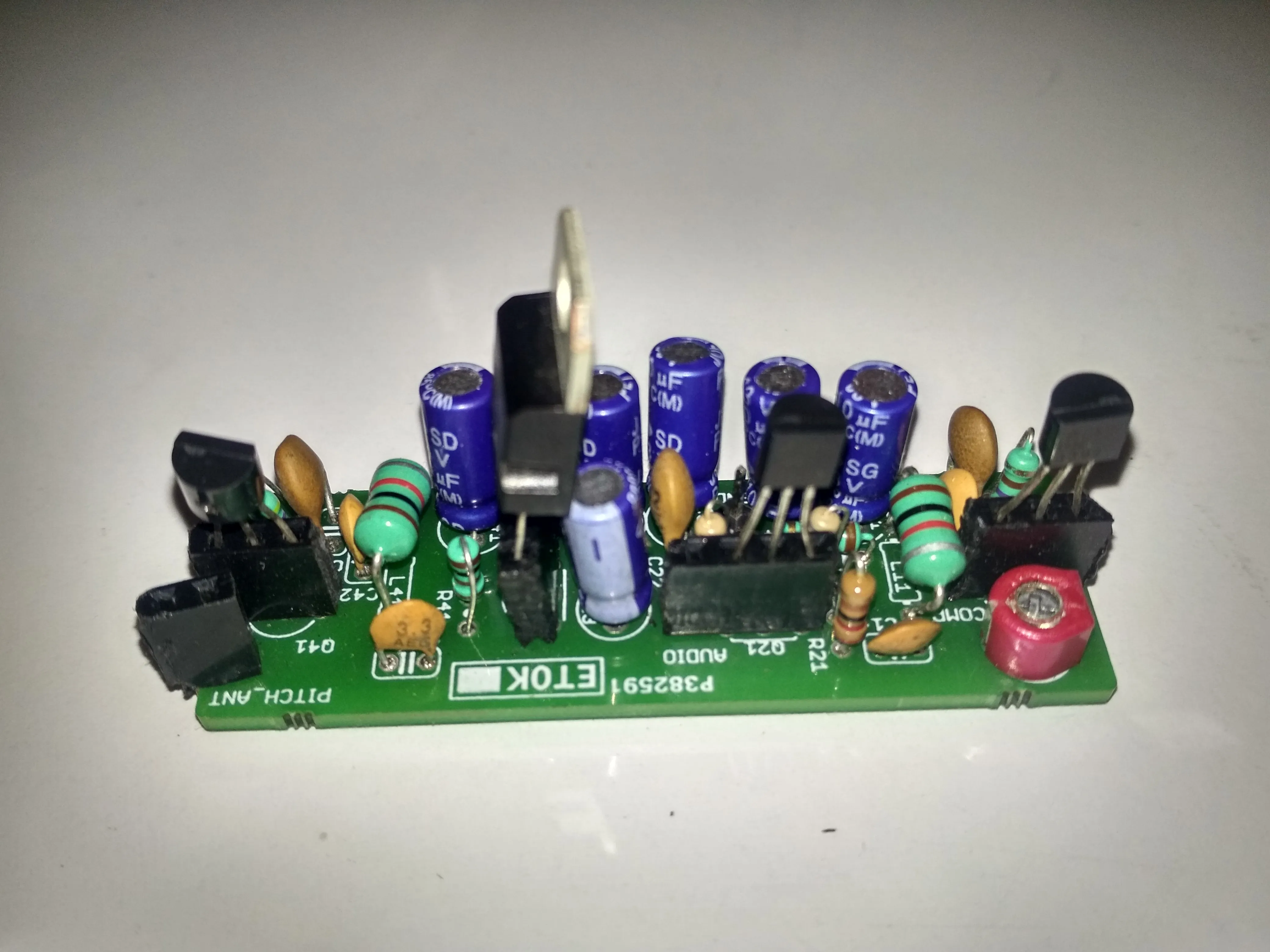
A schematic that works in Multisim and a board that works on your desk are two different problems. We laid the design out in EAGLE, sent it for fabrication, and got back a green two-layer board silkscreened with the net names we’d chosen months earlier — PITCH_ANT, COMP, AUDIO — which turned an abstract net list into something you could point at with a soldering iron.
Tuning it by ear, then by oscilloscope#
With the antenna in — a 50 cm telescopic rod, extended fully except the last, thinnest segment pulled to about half — the last step was purely mechanical: adjust the variable capacitor on the reference oscillator until silence falls at roughly 50 cm from the antenna, then fine-tune by sliding that last antenna segment a few millimeters at a time. Too little travel and the whole playable range is a couple of inches; too much and the pitch field goes so wide it’s unplayable.
Once it held still, we measured it properly instead of trusting our ears:
| Distance from antenna | Beat frequency | Output amplitude |
|---|---|---|
| 3 in | 1500 Hz | 250 mV |
| 4 in | 600 Hz | 400 mV |
| 5 in | 300 Hz | 600 mV |
| 6 in | 190 Hz | 750 mV |
| 7 in | 110 Hz | 900 mV |
The frequency column is the part that makes the physics real: it isn’t linear. Pull your hand back by one inch near the antenna and the pitch collapses by 900 Hz; pull back an inch further out and it only drops by 80. Capacitance falls off sharply with distance, and the oscillator inherits that non-linearity directly — which is also exactly why theremin players talk about the instrument having a “hot zone” close to the antenna where a millimeter of hand movement is a full semitone, and a much gentler slope further out.
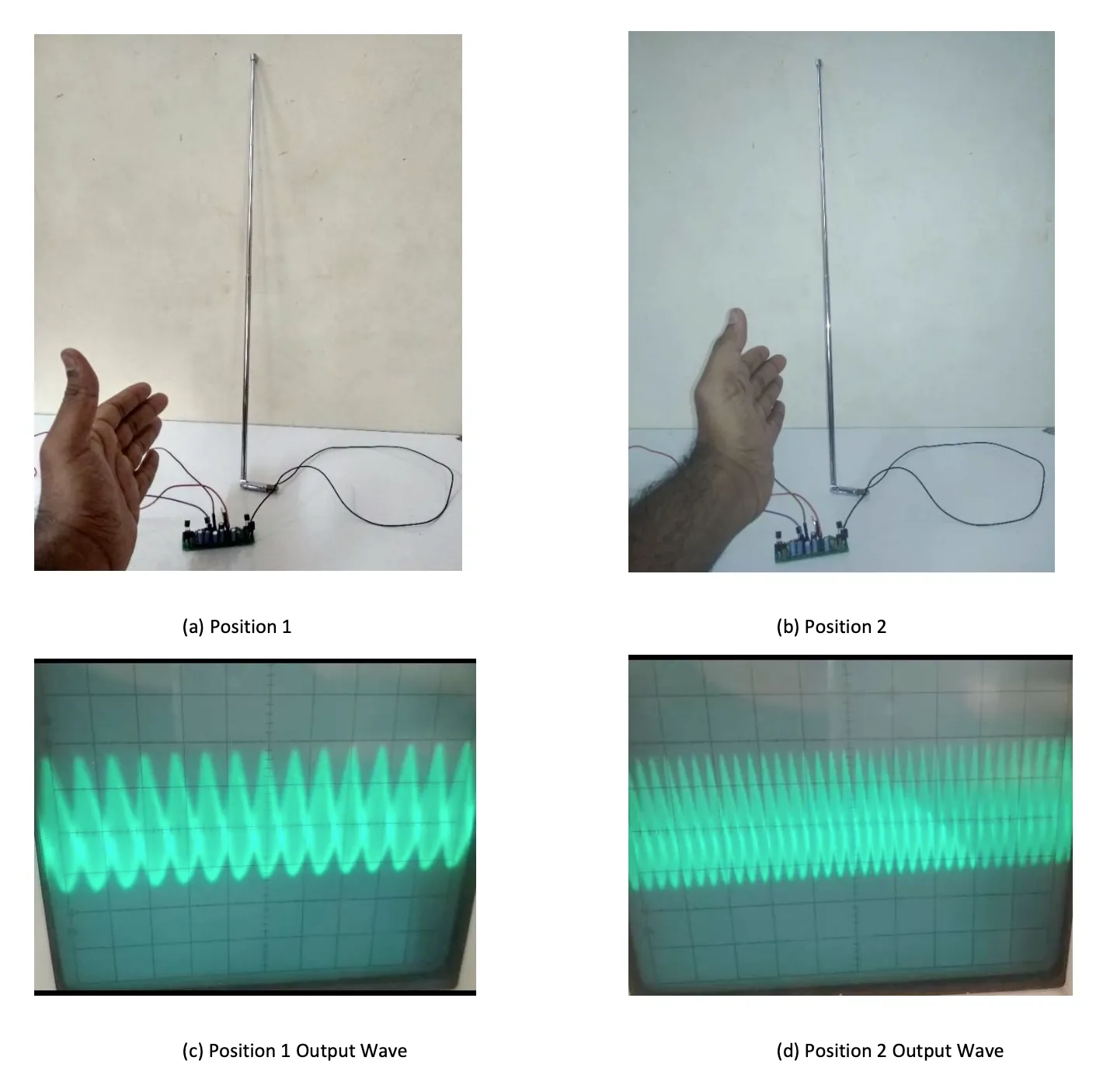
Neither trace is the clean sine wave the diagrams above imply. That’s the active rectifier again — it recovers the beat frequency, but it recovers it shaped, closer to a sawtooth than a sine, which is honestly part of what makes an analog theremin sound like one instead of a lab tone generator.
What it couldn’t do#
It was never going to be a Carolina Eyck concert. The pitch field is omnidirectional, so anything that moves near the bench — another hand, a laptop lid, a person walking past — reads as a phantom pitch bend, and there’s no shielding it away short of a Faraday enclosure we never built. Playing it accurately took real practice; unlike a fretted instrument there’s no physical stop telling you where a note lives, only your ear and muscle memory for a distance in open air. And going pitch-only meant every note played at the same volume — the instrument could bend, but it couldn’t breathe.
Here’s what it sounds like when someone actually can play it like that — Carolina Eyck herself:
None of that made it less satisfying to point a soldering iron at a stack of transistors and get a sound out of thin air. I ended up on the software side of engineering, but I still think about this project every time something claims to be simple and turns out to be two oscillators arguing with each other underneath.
Sources: Theremin instrument — how it works without touch, How Theremins Work, Thereminvox, Theremin, Wikipedia.
Years later this same idea came back as software: Etherpad, a touch synthesizer where fingers replace hands in open air — no antenna, same ethereal music.
Comments
Signed in with GitHub. Be kind.